 Click on all photos for larger view.
Back to Frequently asked questions
Courtesy of Hans Vaalund
© 2005, FirstFives.org™
This is a simple description on how to interface the engine wiring of an E28 engine to a E12 car. It is based on my experiences of adding the electrical fuel system from a E28 518i to my E12 520 with an M10 engine. I have also verified this with different wiring diagrams and think it will cover all E12 models and E28 with L-jetronic and Motoronic.
The electrical interface between the engine and the car is fairly simple. The fuse box connector contains all the signals between the engine and the car on the E12. The E28 engine wiring also has a small interface connector next to the ECU.
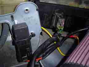
Step one, fuse box connector: Make sure to get an E28 engine with complete wiring. Keep the ignition unit and combo relay(for the fuel pump and injectors) from the E28 wiring. The fuse box connector will not fit the E12, cut it off! Cut all the wires close to the connector. Get a new E12 fuse box connector, or reuse the old one. I removed all the connector pins from the old connector and just used the connector housing. Then I mounted new 1/4" tab connectors (the flat type with crimp tube and melting glue) on the wires and put them into the connector housing(see picture). Note from Peter Florance: "You can purchase tab connectors with the locking tabs from Molex and Amp but they do require special 'roll crimper'." I secured them with melting glue, too be able to remove them later. The pin numbers are marked on the connector housing.
 Click on all photos for larger view.
Here is the list of which wires to put where:
| Pin number: | E28 wire color: | Function: | ||
| 1 | black/yellow | Starter solenoid voltage | ||
| 2 | note 1 | Ignition voltage, fuse 1, to combo relay | ||
| 3 | blue | Charge warning light | ||
| 4 | green | Ignition voltage | ||
| 5 | note 2 | Coil -, to tachometer | ||
| 6 | brown/white | Temp gauge sensor | ||
| 7 | brown/green | Oil pressure switch | ||
| 8 | note 3 | Input power combo relay, fused |
Note 1: This pin is not used.
Ignition voltage on the E28 is supplied to the combo relay by the
green wire on the small connector next to the ECU. I just cut
open the wiring tube a little bit from the combo relay, cut the
green wire(pin 15 on the combo relay), stripped the green wire on
the fuse box connector(pin 4) a bit and soldered the wires
together. I then isolated them and taped all the wires together
again. The combo relay pin 15 can be connected otherways, but it
needs to be connected to the ignition!
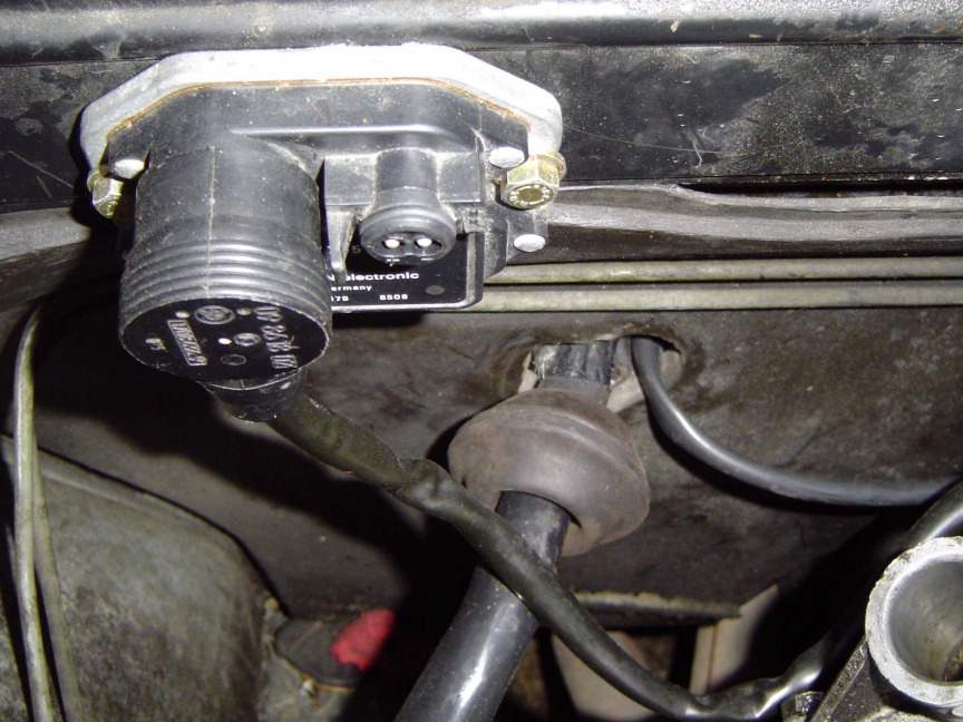
Note 2: The E28 gets the
ignition signal to the tachometer from the ignition module and
not directly from the coil. The E28 the ignition signal is
connected to the instrument panel by the small wiring harness
connector next to the ECU. If your E12 has a tachometer, you need
to make a new connection from the coil to pin 5 on the fuse box
connector. It can be connected directly to the negative pin of
the coil or the center pin of the black wire on the diagnostic
connector.
Note 3: On the E28 the input
power on the combo relay is connected directly to the battery.
Leave it like this! Pin 8 on the fuse box connector is not used.
Step two, ECU (electronic control
unit): If the car already has electronical fuel injection, just
replace the old ECU with the new from the E28 engine. If not,
make a hole on the firewall (app. 50mm) to fit the large rubber
grommet on the cable. Remove the glove box and mount the ECU
under the dashboard.
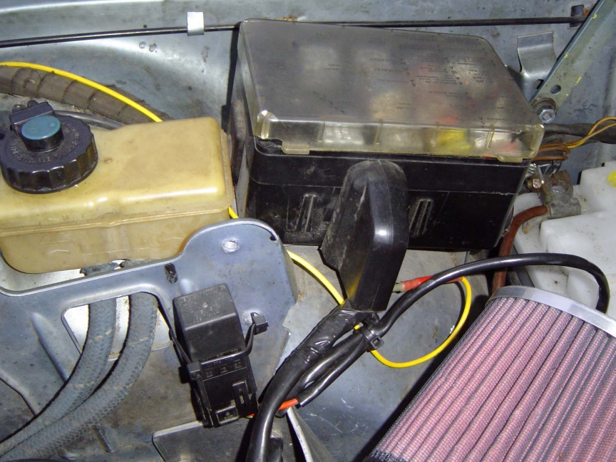
Step three, combo relay: Mount the combo relay somewhere near the fuse box. The connector 87b with the green/violet wire is the power supply to the fuel pumps. Connect this to wire for the fuel pumps in the car. This is not located on the fusebox. I had to install in a new wire to the trunk, yellow wire on the pictures.
Step four, finish it: Use
cable ties and secure all loose wires. Keep the diagnostic
connector if you want. Not very useful, but nice for turning the
starter when working with the engine(by connecting the black/yellow
wire to battery +). Connect the combo relay to the battery
connector. Connect the battery. The ignition can be checked
without the ECU connected. Connect a strobe light, turn on the
ignition and verify that you gets spark and the timing is correct.
Verify that the fuel pumps are running 1-2 seconds after the
ignition is turned on, and then stops. If everything else on the
engine is in place, connect the ECU and try to start it up.
Good luck!
Disclaimer: I have not verified this
modifications with US car wiring diagrams. There could be some
variations that I am not aware of. Check the connections yourself
with a multimeter to make sure everything is correct. See the connector pinout list (PDF file) if you want to learn
more about the wiring on the different connectors.
Sources of information:
http://www.firstfives.org/faq/ljet/ecu_pinout.html
Haynes Owners Workshop Manual BMW 520i & 525e 1981-1988
My car, 520i 1975
EFI system from a E28 518i 1985
List of e12 and e28 connector pinouts (PDF file)