FirstFives.org™
L-Jetronic Throttle
FAQ
Updated
May 19, 2003
Peter Florance
With help from Don
Daynes and Jim Davis
Back
to FAQ list
Background
I decided to put this FAQ together after seeing and
hearing (on the web board) how misunderstood the L-Jetronic
throttle assembly was. Yet it has a few key components and
functions that are critical to the operation of the engine and
fuel injection. I often have seen them in poor repair and
maladjusted. This FAQ will explain how the throttle body works,
how to clean and maintain it and how
to perform the throttle body adjustment
and the throttle switch
adjustment. I suggest the throttle repairs and adjustments be
done before making other engine checks and adjustments. This is
because while there really isn't anything else on the car that
will effect the throttle adjustments; the throttle adjustments
themselves effect other engine tune-up adjustments. So do this
first - then you can forget about it for a long while (just clean
and check it as part of a major tune-up).
Theory of operation
The throttle assembly on the L-Jet system is very
similar to the throttle of a carburetor. The engine is basically
an air pump like a vacuum cleaner. You can think of the manifold
as the vacuum cleaner hose and the throttle as your hand over the
hose of the vacuum cleaner. Opening the throttle is like moving
your hand off the hose, allowing more air to enter the engine,
and the engine to make more power.
The throttle contains the plate itself, switches to tell the fuel
injection system what state it's in (idle, cruise or wide-open
throttle), vacuum ports for advance and retard, and a coolant
chamber at the bottom to warm the throttle body.
At idle, the idle switch is closed by a plastic actuator on the
side of the throttle assembly. When the ecu detects that the idle
switch is closed, it richens the mixture for smoother idle (this
has been debated about US lambda controlled units - right now I
couldn't say for sure). At wide open throttle (yeehaw zone), the
WOT switch is closed signaling the ECU to set the fuel injection
to a fixed quantity, independent of the position of the air flow
meter. This is a slightly rich max power mixture (for
passing etc.).
The other function of the idle
switch on later models is fuel cut-off during coasting (over-run
condition). This fuel cut-off occurs until the engine RPM fall to
a set value at which point fuel is restored for idle condition.
ECU's ending in 108,111, and 114 (euro models) have this rpm set
to 3000 and use the enclosed throttle switch assembly (not shown
at this time). ECU's ending in 118 and 122 have this rpm set to
1200 and use the exposed dual micro-switch assembly (shown under Throttle Switch Adjustment).
Other ecu's with lower numbers do not appear to have this feature.
This would include early and later 530i models.

Fuel cut-off (over-run) for certain models
When the throttle is closed, the vacuum advance port on the top
of the throttle is connected internally to a very small hole just
in front of the top of the throttle plate. At idle, the hole is
at atmospheric pressure as it’s outside of the manifold.
Once the throttle is opened slightly the plate moves forward past
the hole. Because the amount of air entering the engine is still
small, the manifold and the volume behind the plate where the
advance port is located are still under vacuum. This vacuum is
used to pull on the distributor advance diaphragm through the
advance port and hose, which rotates the distributor advance
mechanism in the advance direction. This throttle-activated
advance improves responsiveness and fuel economy. Note on the US
528i, the advance hose is connected through a temperature-actuated
valve (green, 2 port device) located on the thermostat housing.
The valve is closed until the coolant is warm, defeating advance
during warm-up. My valve doesn’t work (it's stuck open and I
haven’t had a chance to change it yet - 4/6/2001) and my
engine pings a little until warm.
The vacuum retard port on the bottom of the throttle body is
connected internally to a very small hole just behind the bottom
of the throttle plate. At idle the retard port is exposed to
vacuum and is used to rotate the distributor advance mechanism in
the retard direction. As the throttle moves open, it moves behind
the retard port, exposes the retard port to atmospheric pressure,
eliminating the vacuum retard or in effect, advancing the timing
from idle. In this sense, the vacuum retard and advance
accomplish the same thing. In fact, the US 530i has only vacuum
retard and the 80-81 US 528i has only vacuum advance. 79 US 528i
appears to use both, possibly with a different distributor.
Maintenance
Making sure the throttle is in good shape means it’s clean,
tight and adjusted properly. This will insure good drive-ability.
I recommend making sure the throttle and throttle switches are
adjusted properly before trying to tune the car (timing or
mixture) as operation of the throttle switches (idle and wide-open-throttle
mixture) and distributor vacuum ports are effected by the
operation of the throttle.
Check the throttle for looseness at the linkage bushings. The two
bushing are available and there are some small shims to take up
slack. It was tight once, so if it's loose now and no one has
taken it apart, the nylon bushings are probably worn and will
need to be replaced. My guess it you won't need to re-shim the
pivot bushings, that's probably only for variations in the
aluminum casting size. Also check for leaks at the coolant
chamber. The throttle shown below had chronic leaks at the hoses
and gasket. The bolts were rusted and one of the hose connections
was corroded away. It's about a $65.00 part from your dealer.
Check the switches with an
ohmmeter to make sure they close when the metal tab on the switch
is depressed. An audible click will also let you know the ‘snap’
action of the switch is still working. If either of the switches
fails to show continuity or snap when pressed, replace it . Note
the idle and WOT switches are different.
 |
| Throttle shown from air flow meter
side |
 |
| Throttle shown from top |
Adjustment:
To adjust the throttle body, you’ll need to
remove the AFM and hose so you can see the throttle plate.
Loosen the idle stop screw lock nut.
Unscrew the idle stop screw until it’s
flush with the casting of the throttle body so it doesn't
effect the throttle position.
Loosen the 8mm throttle plate lock screw
on the throttle plate shaft. You'll see the head from the
passenger side looking on the side of the throttle. With
this loose, the plate will now move independently from
the shaft.
Manually open the plate by pressing
inward on the lower half of the plate and inspect it and
the throttle housing inside edges. If it's dirty, clean
it with a rag and carburetor cleaner. It's important that
the edges of the throttle plate and the area of the
throttle housing where it rests are both very clean for
this adjustment to work well.
While pressing the throttle plate shut (by
pressing in on the top half of the throttle plate),
adjust the idle stop screw until the roller is 0.5 to 1.0
mm below the top of the gate it rides in.
Whill still holding the throttle plate
shut, tighten the 8mm throttle plate lock screw on the
throttle shaft. You can now release the plate. It will be
spring-loaded shut.
Turn the idle stop screw one more turn
clockwise (opening the throttle plate slightly).
Lock the nut on the idle stop screw by
tightening it against the throttle body (just snug is
fine). Never use the idle stop screw to set idle
speed - use the throttle bypass screw (below throttle
switches).
Once you've adjusted the throttle body, you'll need to adjust the throttle
switches (below section). After that you can proceed
with tune up including idle speed adjustment.
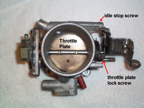 |
Throttle assembly
shown from air flow meter side.
Photo by Peter Florance |
 |
Adjustment of idle stop screw (looking from firewall
forward). Note the gap between the roller and the top of
the gate or track it rides in
Photo by Peter Florance |
Throttle Switch Adjustment - (under construction) Once the throttle body adjustment is completed, the throttle switches
should be checked and adjusted as needed. Unplug the two
connectors on the idle switch and connect each lead of an
ohmmeter to a terminal on the idle switch. Set the ohmmeter to
200 ohm or lower resistance scale or continuity scale. It's not
important which color lead goes on which terminal. Loosen the two
switch plate lock screws until the switch plate can be rotated
back and forth. Rotate the switch plate counter-clockwise until
the meter reads infinite or no continuity. If you not sure what
this reading should look or sound like on your ohmmeter, check
the owner's manual for your ohmmeter. Then rotate the plate
clockwise until the meter reads continuity. You ought to read
less than 10 ohms. More than that and you may have a problem with
the switch. Then tighten the plate and re-connect the idle switch
connectors. Then remove the WOT switch connectors. Connect your
ohmmeter to the WOT switch terminals as you connected it to the
idle switch. Verify that the meter reads open when at idle but
that it will read continuity when the throttle is wide open (open
the throttle linkage with your hand - don't use the throttle
plate to open it) and the actuator contacts the WOT switch lever
(shown below). The best off-results are obtained when the switch
just closes as the throttle reaches idle. Re-connect the WOT
switch connectors and proceed with your tune-up.
The enclosed-type throttle switches are adusted in a similar
manner. The cover is plastic and comes off with hooks on the top
and bottom edges. Once the cover is removed you can see the
common, idle, and WOT contacts and the operation of the switch.
To adjust the enclosed switches, loosen the mounting screws and
adjust the entire switch assembly in the same manner the external
switches are adjusted (above). Note the enclosed switch does not
work well with 118 or 122 ECU's.
Additional note: Adjusting the switch plate so
the idle switch just reliably closes when the throttle switch is
closed seems to provide the smoothest off idle response on lambda
systems (US 528i etc).
 |
|
Throttle switches
Idle on right, wide-open-throttle (WOT) on the left. |
|
Back
to FAQ list
© 2001, FirstFives.org™